When it comes to navigating the vast waters, having a reliable GPS system is crucial for any boater or fisherman. Lowrance GPS antennas are renowned for their precision and accuracy, providing users with a seamless experience on the water. However, setting up these systems can be a daunting task, especially for those without extensive technical knowledge. This is where a comprehensive wiring diagram comes into play, ensuring that every component is properly connected and functioning as intended.
Lowrance GPS Antenna Wiring Diagram is a detailed guide that breaks down the complex process of connecting your GPS antenna to your Lowrance device. With this diagram, you'll be able to troubleshoot any issues and ensure your system is running at optimal levels. The diagram includes step-by-step instructions and detailed illustrations, making it accessible to users of all skill levels. Whether you're a seasoned pro or a beginner, this wiring diagram is an essential tool for anyone looking to get the most out of their Lowrance GPS system.
what is the purpose of the lowrance gps antenna wiring diagram
 The purpose of the Lowrance GPS antenna wiring diagram is to provide a detailed guide for connecting and setting up the GPS antenna with the Lowrance device. This diagram helps users ensure that all components are properly connected and functioning as intended, which is crucial for accurate navigation and optimal performance of the GPS system.
how to connect the lowrance gps antenna to a boat's electrical system
 To connect the Lowrance GPS antenna to a boat's electrical system, you will need to follow these general steps:
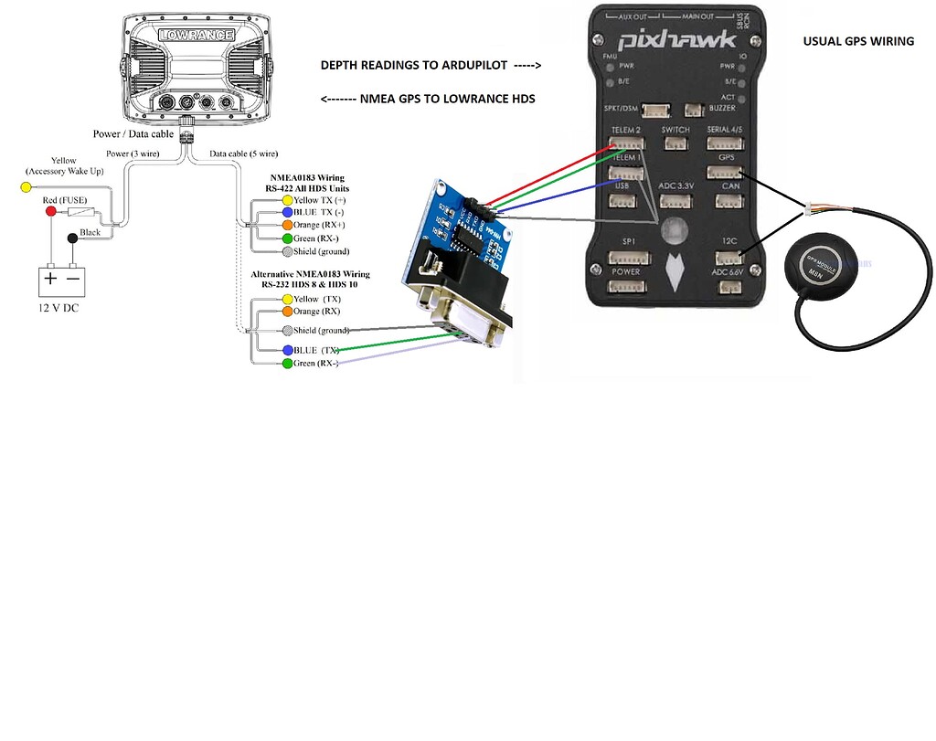
Identify the Power Source: Determine the power source for your GPS system. Typically, this is the boat's main power cord, which usually has a dedicated circuit for the electronics. Ensure that this circuit is capable of handling the power requirements of your GPS system.
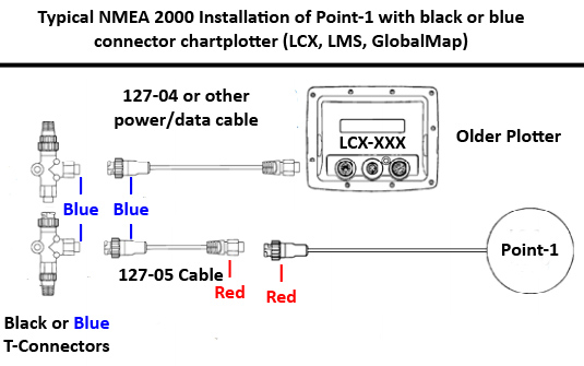
Locate the NMEA Network: Find the NMEA 2000 network on your boat, which is usually connected to the main power cord. This network is responsible for transmitting data between devices, including the GPS antenna.
Connect the NMEA Cable: Connect the NMEA cable from the GPS antenna to the NMEA 2000 network. This cable provides power to the GPS antenna and allows it to transmit data to the boat's electronics.
Power the GPS Antenna: Ensure that the GPS antenna is properly powered. If your boat's electrical system is capable of handling it, you can run the NMEA power always hot, without a switch. However, if you prefer to conserve power, you can run it through a switch to turn it on and off as needed.
Mount the Antenna: Mount the GPS antenna securely on the boat, either pole-mounted or surface-mounted, depending on the type of antenna and your boat's design. Ensure that the antenna is fully waterproof and protected from the elements.
Configure the GPS System: Configure your GPS system according to the manufacturer's instructions. This may include setting up the antenna, configuring the display, and ensuring that the GPS system is properly integrated with other boat electronics.
By following these steps, you should be able to successfully connect your Lowrance GPS antenna to your boat's electrical system, ensuring accurate navigation and optimal performance of your GPS system.
To connect the Lowrance GPS antenna to a boat's electrical system, you will need to follow these general steps:
Identify the Power Source: Determine the power source for your GPS system. Typically, this is the boat's main power cord, which usually has a dedicated circuit for the electronics. Ensure that this circuit is capable of handling the power requirements of your GPS system.
Locate the NMEA Network: Find the NMEA 2000 network on your boat, which is usually connected to the main power cord. This network is responsible for transmitting data between devices, including the GPS antenna.
Connect the NMEA Cable: Connect the NMEA cable from the GPS antenna to the NMEA 2000 network. This cable provides power to the GPS antenna and allows it to transmit data to the boat's electronics.
Power the GPS Antenna: Ensure that the GPS antenna is properly powered. If your boat's electrical system is capable of handling it, you can run the NMEA power always hot, without a switch. However, if you prefer to conserve power, you can run it through a switch to turn it on and off as needed.
Mount the Antenna: Mount the GPS antenna securely on the boat, either pole-mounted or surface-mounted, depending on the type of antenna and your boat's design. Ensure that the antenna is fully waterproof and protected from the elements.
Configure the GPS System: Configure your GPS system according to the manufacturer's instructions. This may include setting up the antenna, configuring the display, and ensuring that the GPS system is properly integrated with other boat electronics.
By following these steps, you should be able to successfully connect your Lowrance GPS antenna to your boat's electrical system, ensuring accurate navigation and optimal performance of your GPS system.what tools are needed to connect the lowrance gps antenna to a boat's electrical system
To connect the Lowrance GPS antenna to a boat's electrical system, you will typically need the following tools: Drill and drill bits: For drilling holes in the boat's structure to accommodate the antenna's mounting hardware2. Wire strippers: To strip the insulation from the ends of the cables connecting the GPS antenna to the boat's electrical system2. T-connectors: For connecting the GPS antenna to the NMEA 2000 network, which is usually part of the boat's electrical system2. Resistors: To ensure proper termination of the NMEA 2000 network, which is crucial for the GPS antenna to function correctly2. Screws and fasteners: For securing the GPS antenna to the boat's structure, such as the pole or surface mount. Power source: Access to the boat's electrical system, typically through the main power cord, which provides power to the GPS antenna2. NMEA 2000 micro-C port: For connecting the GPS antenna to the NMEA 2000 network, which is usually part of the boat's electrical system. NMEA 2000 cable: For connecting the GPS antenna to the NMEA 2000 network, which transmits data between devices. Calibration tools: For calibrating the GPS antenna, which may involve disconnecting and reconnecting sensors, as well as ensuring proper alignment of the antenna2. These tools are essential for ensuring a secure and functional connection between the Lowrance GPS antenna and the boat's electrical system.
Lowrance Gps Antenna Wiring Diagram
. wiring schematic - An Overview So let’s get For example our heat, that's our to start with a single, B and A. Now if we glance at B plus a and if a customer claims, “Hey, in my car-dry cycle, my dresses remain popping out sopping damp. It’s not drying in any respect,” what I'd personally wish to do is, first of all, Check out electrical power towards the device. Question: I've can lights in an old household the common wire is incredibly hot. The can lights are on A 3 way switch. How am i able to get my my widespread wire again? Response: The widespread wire may be useful for the a few way switching, and this is typical, not that the prevalent is switched, but that the "white wire" which appears like a standard is useful for switching.

Lowrance Gps Antenna Wiring Diagram
. To examine these diagrams, begin at the facility resource and Keep to the line as a result of every one of the elements of the procedure. JYeltonJYelton 29k3333 gold badges128128 silver badges239239 bronze badges $endgroup$ 1 3 $egingroup$ When you finally see why we want schematics as apposed to other kinds of diagrams, see also electronics.
Lowrance Gps Antenna Wiring Diagram
Just what exactly I want to do here is we’re intending to go on and I’m likely to go in excess of the various things within the schematic and we’re planning to trace out very first our warmth circuit. Alright. So what I’m intending to do is I have this schematic in a plastic sleeve. That is most likely amongst the best stuff you can perform once you’re seeking to determine a schematic in the customer’s property. Electrical change diagrams which have been in shade have a benefit in excess of ones that are black and white only. Therefore the circuit higher than when defined must give you a good notion on how this four-way circuit operates. When wiring a 4-way switch, this picture on the remaining will show how the connections must really appear when all connections are created.
Lowrance Gps Antenna Wiring Diagram
But I need to go ahead and move on with this particular Esterline chart and I choose to drop by B and C, which are going to be to the motor. And the heater as well as motor During this video clip are two major targeted merchandise that we wish to evaluate, Which we wish to truly be capable to trace out so you're able to see how electrical power will get there using the 240 volts. Hey, what’s happening All people, Tim with Fred’s Equipment Academy, here with another wonderful video clip in your case right now. Within this video clip, we’re likely to go around 240-volt Frigidaire electrical dryer which has a mechanical model timer on it, And that i’m going to instruct you how to go in excess of the schematic and how to read through the schematic and understand the schematic, that by the point this video is about and carried out with once we trace out the particular circuits for the heat and also the motor, you’re likely to take a look at points and have the capacity to form of simplify if you’re out in the field.
Lowrance Gps Antenna Wiring Diagram
Keep your diagram nearby. You will need to refer to it typically as you're employed on your own venture. Once the electrical venture is finished the diagram is going to be handy for screening and troubleshooting the circuit. Directory of Wiring Diagrams A schematic is defined as a picture that reveals some thing in an easy way, employing symbols. A schematic diagram is a picture that signifies the parts of the process, system, or other object applying abstract, normally standardized symbols and contours. The 4-wire link is the new updated circuit. The only difference is the addition of the isolated floor wire independent through the neutral as described previously.
Web Lowrance Gps Antenna Wiring Diagram Wiring Diagram Honda Photobucket Gx240 I7 Garmin Striker Charvel Version Source.
Lowrance hook2 cruise power cable for. Lowrance antenna point gps nmea 2000 installation box cable lgc glonass connect. Gm480c/gm540c have 12v cigar cables and you don't have to worry about this.
Lowrance Gps Tech Lowrance Gps Wiring.
Web lowrance gps antenna wiring diagram wiringall.com. Lowrance antenna point gps nmea 2000 installation box cable lgc glonass connect. Web diagram dodge journey antenna wiring gps need stereo found.
Lowrance Hds 7 Wiring Diagram.hereby, Navico Holding As Declares That This Hds Is In Compliance.
Web navman vhf interfacing manualzz [yv_4573] navman gps wiring diagram download diagram. Web lowrance gps antenna wiring diagram wiringall.com. Lowrance elite 5 hdi wiring.
Web Lowrance Wiring Gps Radio Data Connecting Wire M7 Db9 Unit 540C Shield Tracking 2009.
Web the parts needed for mounting the module on a. Lowrance power cable with vider. Lowrance lms 520c wiring diagram wiring diagram is a simplified gratifying pictorial representation of.
Lowrance Elite 5 Hdi Wiring.
Web lowrance 2000 nmea wiring diagram lms lgc 337c gps 522c connector connected module marine electronics igps question ask own. Navman vhf interfacing manualzz [yv_4573] navman gps wiring diagram download diagram. Lowrance gps antenna wiring diagram from wiringall.com lowrance gps antenna wiring diagram.
As you navigate through the vast waters, having a reliable GPS system is crucial for any boater or fisherman. Lowrance GPS antennas are renowned for their precision and accuracy, providing users with a seamless experience on the water. However, setting up these systems can be a daunting task, especially for those without extensive technical knowledge. This is where a comprehensive wiring diagram comes into play, ensuring that every component is properly connected and functioning as intended. The Lowrance GPS Antenna Wiring Diagram is a detailed guide that breaks down the complex process of connecting your GPS antenna to your Lowrance device. With this diagram, you'll be able to troubleshoot any issues and ensure your system is running at optimal levels.
Whether you're a seasoned pro or a beginner, this wiring diagram is an essential tool for anyone looking to get the most out of their Lowrance GPS system. By following the steps outlined in the diagram, you'll be able to ensure that your GPS antenna is properly connected and functioning correctly. This is crucial for accurate navigation and optimal performance of your GPS system. Remember, a well-connected GPS antenna is the key to a successful and enjoyable boating or fishing experience. So, take the time to review the Lowrance GPS Antenna Wiring Diagram and ensure that your GPS system is running at its best. With this diagram, you'll be able to unlock the full potential of your Lowrance GPS system and enjoy the thrill of navigating the open waters with confidence.


No comments:
Post a Comment